Ultrasonic Meter Type
Water Meter
uFlow 350W SERIES (DN15-300)
1. Introduction
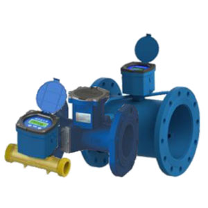
The uFlow 350W series type ultrasonic water is an innovative flow meter with static flow sensor based on the ultrasonic measuring principle. It utilizes ultrasonic measuring methodology and microprocessor technology. All calculation and flow measuring circuits are designed on one single board, thus offering exceptional accuracy and reliability.
2. Features
- Double beam ultrasonic sensors for high accuracy and reliable operation
- Less than 0.01 m/s starting velocity
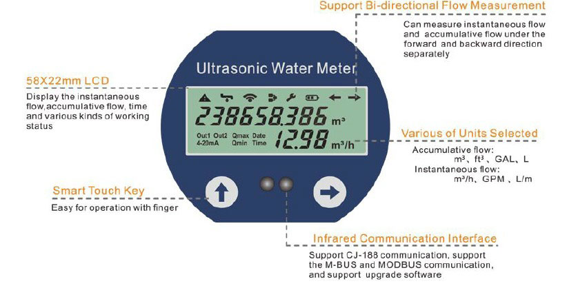
- Multi line 9 digital LCD accumulative flow and 4 digital for instantaneous flow
- Automatic power saving function under the empty pipe or long-term fluid stationary state
- IP68 protection, ensure long-term operation though water in the inside meter
- Date cumulative record and data acquisition function
- Various kinds of communication interface:TTL levels pulse output and USART interface,convenient to connect the low power consumption equipment; RS485; Infrared
communication interface; support CJ-188 communication - Support MODBUS,M-BUS ,HART communication protocol
- Output: Two way isolated pulse output(pulse equivalent and output pulse can be arbitrary programmed); two-wired system 4-20mA output
- With the two way PT1000 temperature transducer, which can realize the heat measurement
- Built-in batch controller and time accumulator
- Various of Units selected, including Cubic meter, USA gallon, Cubic feet and Liter
- Built-in Lithium battery for 6 years life
3. Application
- Residential water meter
- District water meter
- Tenant billing
4. Display and Operation
5. Communication and Signal Output
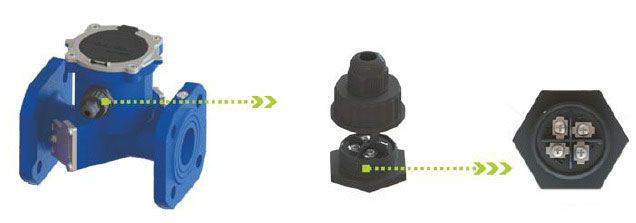
* There are 4 terminals Available
Standard Configuration:
- RS485+ (A)
- RS485- (B)
- DC8~30V
- GND
Optional:
- OCT 1
- OCT 2
- C1 (TTL output 1)
- C2 (TTL output 2)
- 2 wired 4-20mA (Also function as external power supply 24V DC)
NOTE: When ordering, you may choose any two of the above output or interface, lead to the external junction.
6. Dimensions
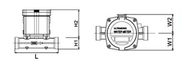
DN15 – 40
| Size (mm) | Pressure MPa | Dimension | ||||||
|---|---|---|---|---|---|---|---|---|
| L(mm) | H1(mm) | H2(mm) | W1(mm) | W2(mm) | Screw Thread | Screw Thread Coupling | ||
| 15 | 1.6 | 110 | 17.5 | 168 | 58 | 90 | G3/4B | R1/2 |
| 20 | 130 | 24 | 173 | 58 | 90 | G1B | R3/4 | |
| 25 | 160 | 25 | 175 | 58 | 90 | G1 1/4B | R1 | |
| 32 | 180 | 31 | 177 | 58 | 90 | G1 1/2B | R1 1/4 | |
| 40 | 200 | 31 | 181 | 58 | 90 | G2B | R1 1/2 | |
DN15 – 40
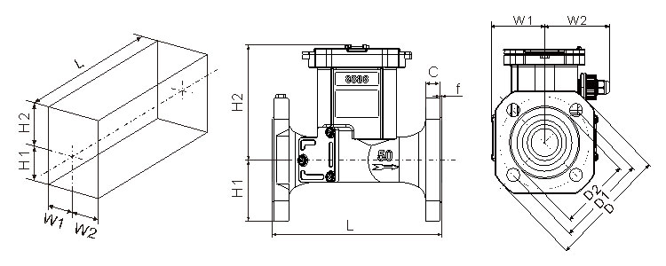
| Size (mm) | Pressure MPa | Dimension | Flange Dimension | |||||||||
|---|---|---|---|---|---|---|---|---|---|---|---|---|
| L(mm) | H1(mm) | H2(mm) | W1(mm) | W2(mm) | Flange Diameter D | Bolt Center D1 | Bolt hole x Quantity Ф x n | Sealing Surface | Flange Thickness C | |||
| 50 | 1.6 | 200 | 70 | 131 | 76 | 95 | 165 | 125 | 18×4 | 102 | 2 | 19 |
| 65 | 1.6 | 200 | 75 | 135 | 79 | 95 | 185 | 145 | 18×4 | 122 | 2 | 20 |
| 80 | 1.6 | 225 | 94 | 132 | 94 | 95 | 200 | 160 | 18×4 | 138 | 2 | 20 |
| 100 | 1.6 | 250 | 104 | 140 | 104 | 104 | 220 | 180 | 18×4 | 158 | 2 | 22 |
| 125 | 1.6 | 275 | 117 | 148 | 117 | 117 | 250 | 210 | 18×4 | 188 | 2 | 22 |
| 150 | 1.6 | 300 | 134 | 155 | 114 | 114 | 285 | 240 | 18×4 | 212 | 2 | 24 |
| 200 | 1.6 | 350 | 165 | 254 | 165 | 165 | 340 | 295 | 22×12 | 268 | 2 | 26 |
| 250 | 1.6 | 450 | 197 | 269 | 197 | 197 | 405 | 355 | 26×12 | 320 | 2 | 29 |
| 300 | 1.6 | 500 | 223 | 287 | 223 | 223 | 460 | 410 | 26×12 | 370 | 2 | 32 |
7. Flow Range
| Size (mm) | Ratio | Flow (m3/h) | ||||
|---|---|---|---|---|---|---|
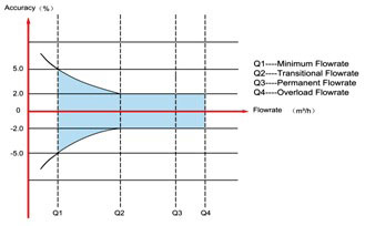
| Starting Flowrate | Minimum Flowrate Q1 | Transitional Flowrate Q2 | Permanent Flowrate Q3 | Overload Flowrate Q4 | ||
| 15 | 200 | 0.003 | 0.0125 | 0.02 | 2.5 | 3.125 |
| 20 | 200 | 0.0035 | 0.016 | 0.026 | 3.2 | 4 |
| 25 | 200 | 0.007 | 0.02 | 0.032 | 4 | 5 |
| 32 | 200 | 0.01 | 0.032 | 0.05 | 6.3 | 7.875 |
| 40 | 200 | 0015 | 0.1 | 0.16 | 20 | 25 |
| 50 | 100 | 0.03 | 0.4 | 0.64 | 40 | 50 |
| 66 | 100 | 0.059 | 0.63 | 1.008 | 63 | 78.75 |
| 80 | 100 | 0.064 | 1 | 1.6 | 100 | 125 |
| 100 | 100 | 0.094 | 1.6 | 2.56 | 160 | 200 |
| 125 | 100 | 0.12 | 2 | 3.2 | 200 | 250 |
| 150 | 100 | 0.27 | 2.5 | 4 | 250 | 312 |
| 200 | 100 | 0.315 | 4 | 6.4 | 400 | 500 |
| 250 | 100 | 0.508 | 4 | 6.4 | 400 | 500 |
| 300 | 100 | 0.77 | 6.3 | 10.08 | 630 | 787.5 |
8. Technical Specification
| PARAMETER | SPECIFICATIONS |
|---|---|
| Medium |
Water, Sewage, Seawater (Other types of liquid need customization) |
| Medium Temperature |
0.1~30°C |
|
Working Environment |
Temperature: ‐10~45°C; Humidity≤100%(RH) |
|
Working Pressure |
1,6MPa (2.5MPa optional) |
|
The Sensitivity of Upstream |
U3 |
|
The Sensitivity of Downstream |
D0 |
|
Climatic and Mechanical |
C class |
|
Electromagnetic Compatibility Class |
E2 class |
|
Communication Interface |
RS485 / USART / Infrared |
|
Output Signal |
Two way OCT pulse output/ TTL pulse output/ One way 4-20mA output |
|
Power Supply |
Built-in Lithium battery (3.6, 19AhV) / DC8~36V power supply |
|
Protection Class |
IP68, can work 2 meters under water |
| Display |
Multi line 9 digits accumulative flow, 4 digital display for instantaneous flow, varies of state prompt and units |
|
Data Storage |
EEPROM/FLASH, automatically record the accumulative flow of last 521 days |
|
Measurement Cycle |
Measuring: 1/second; Verification: 4 times/second |
|
Power Consumption |
≤2.7AH/year, 6 years battery life |
